English
A casting equipment for bamboo fiber degradation materials
Natural bamboo fiber is the most abundant natural polymer material in nature, with a total growth of billions of tons, far exceeding the total reserves of existing oil on Earth. In today's increasingly scarce natural resources, it is urgent to fully utilize natural bamboo fiber resources, leverage their unique functions and characteristics, and develop new application areas. The composite preparation of green composite materials using natural bamboo fibers and biodegradable plastics is one of the effective ways to develop and utilize this resource
Natural bamboo fiber has many advantages such as high aspect ratio, high specific strength, large surface area, low density, low cost, renewability, and biodegradability, making it have good industrial prospects. The development and preparation of environmentally friendly and biodegradable green composite materials using natural bamboo fibers as reinforcement materials and biodegradable plastics as substrates has become a research hotspot in the new century
The present invention relates to a film processing equipment for bamboo fiber degradation materials, which is made of bamboo powder as raw material and added with polymer adhesive. The film is produced by extrusion casting method, and bamboo is used as a new material instead of plastic. It has environmental protection, energy saving, and renewable resources, replacing traditional chemical raw materials and bio based materials in the grain industry. Therefore, the equipment is developed to adapt to the plasticization molding of bamboo fiber materials and improve their quality. It has the advantages of high cost-effectiveness and easy operation, and can be used for mass production, as well as non-standard customization, scientific research and teaching experiments.
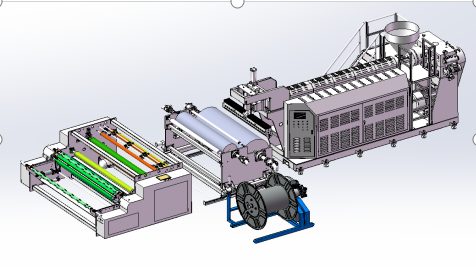
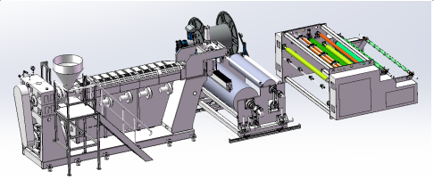
The device structure is as follows:;
S1 extruder; Equipped with a bracket base, hopper, reducer, main motor, screw, screen changer, connector, and mold.
Control electrical box, electrical components.
S2 cooling area; Equipped with track supports. Track wheel, lifting mechanism, cooling roller 1, cooling rod 2, rotating circulation joint,
Guiding rod, cooling roller drive motor, front and rear track movement motor,
S3 waste winding location; Equipped with a bracket to drive the motor. Roll up shaft, electrical control box
S4 winding position; Equipped with traction rollers, traction motors, opening and closing cylinders, slitting knives, pressure sensors, flattening bars,
Guide roller, waste U-shaped wheel, winding rod, flipping knife holder, flying knife cutting, translating material collection, unloading rack, inflation shaft, electrical control, manual interface touch screen
technological process; The S0 raw material enters the hopper and sinks with its own weight. It is driven by a motor to reduce the speed and rotate the extruder screw, pushing the raw material to move along the curve of the screw, heating the solid to form a solution. After passing through the screen changer device, it is pressurized and separated by the mesh, filtering impurities in the raw material. The solution passes through the connector and enters the T-shaped mold.
The S1 mold is installed at a 90 degree angle and adopts a T-shaped hanger structure, gradually dispersing evenly from the middle to both sides to form a continuous film. Vertical angle position with cooling roller No.1
The upper end of the S2 cooling mechanism consists of two cooling rods and two guide rollers, namely cooling rod 1 # and cooling roller 2 #. Rotary circulation joints are installed at both ends of the cooling rod for cooling water rotation and controlling the constant temperature of the roller surface.
Two guide rollers, labeled 1 # and 2 # respectively, guide the direction of the film. The cooling mechanism consists of a motor, a lifting mechanism, a track wheel, a track drive motor, and a track base. It can be adjusted up and down according to the height of the die mouth. The film flows out of the die mouth, passes through two cooling rollers for shaping, and two guide rollers and S-shaped direction enter the coiling traction part. In order to facilitate the cleaning of the die and the operation of the reserved position, rails are added at the cooling part, and the drive motor can flexibly adjust the track wheel and adjust it back and forth. Need to clean or replace the mold. Move the cooling rod forward to clear the space position. When starting up, move the cooling roller backward and adjust it to the desired angle position. Fast cooling rod speed - thin film stretching, slow speed - thick stretching.
After being cooled and shaped in the cooling section, the S3 film enters the traction section. It first passes through a flattening rod, which can adjust the bending angle to eliminate longitudinal wrinkles in the film. Between the traction and winding rods, there is a pressure sensor, an online slitting knife, a flattening rod, and the film enters the traction section. The traction roller is equipped with a cylinder opening and closing for easy film penetration operation. The traction speed is monitored by an encoder to synchronize with the cooling rod speed in real time. If the cooling rod speed is fast, the traction speed will be fast, otherwise it will be slow.
After the film enters the traction, the pressure sensor detects the tension of the film and sets an appropriate tension value. If the tension is too high, the film will stretch too much, causing longitudinal wrinkles. If the tension is too low, it will drift left and right, and the winding end face will be uneven. The CPU calculates and PID adjusts the tension value between the cooling rod and the traction. When the actual value is greater than the set value, the traction speed will automatically slow down. When the actual value is less than the set value, the traction speed will automatically increase, always ensuring a constant tension.
The S5 film is pulled into the winding rod, and the surface wrinkles are eliminated by the flattening rod. The tension of the film is detected by a pressure sensor, and an appropriate tension value is set. If the tension is too high, the film will be stretched too much, causing longitudinal wrinkles. If the tension is too low, it will drift left and right, and the winding end face will be uneven. Due to the increasing diameter of the film roll, the initial tension and the tension changes caused by the change in roll diameter are calculated by the CPU, and the tension value between winding and traction is adjusted by taper calculation. The tension ratio is controlled by the taper closed loop following the size of the roll, ensuring the winding tension demand of bamboo fiber material. Avoid excessive tension, which can cause stretching and material breakage, as well as deformation of the innermost layer material due to compression. Avoid winding deviation and slippage caused by insufficient tension.
S6 rewinding adopts a surface friction structure and is equipped with a tool holder flip, flying knife cutting, translational feeding, unloading bracket, and meter sensor. When the coil reaches the set meter, the tool holder automatically flips to the designated position, and the pre prepared inflation shaft flips to the tool holder position. The top air component supports the tool holder inflation hole on both sides at the same time, and the inflation hole is connected to a rodless cylinder. The rodless cylinder installs the blade, and during inflation, the rodless cylinder runs left and right. After cutting the film, the translational feeding component pushes the coiled film into the unloading bracket. After waiting for a few seconds, it automatically returns to the original position, and the tool holder flips to the original position. The inflation shaft is moved to the translational position to complete the rewinding step.
The S7 unloading bracket is manually inspected or packaged with finished film, and the unloading is manually controlled by placing the coil at the trailer. Ensure the safety of personnel and the packaging of finished rolls.
The electrical installation of the S8 winding part is done inside the winding shell for easy transportation and operation. The electrical control of the extruder is installed on the side of the extruder bracket for easy transportation and operation.